Department of Engineering Workshop Technology
VISION
Workshop Technology Department strives to provide quality technical education and prepare the students to become well qualified engineers competent to face global challenges and to serve humanity by acquiring adequate professional knowledge, skills and training.
MISSION
The Department of Workshop Technology strives to continually engage in:
- Ensuring quality teaching-learning process to provide in-depth knowledge of basic concepts, principles and applications of processes, tools and systems pertaining to Workshop Technology, Production Technology and interdisciplinary areas.
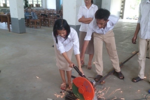
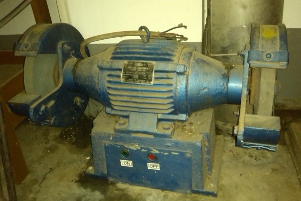
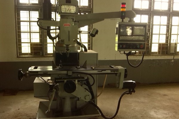
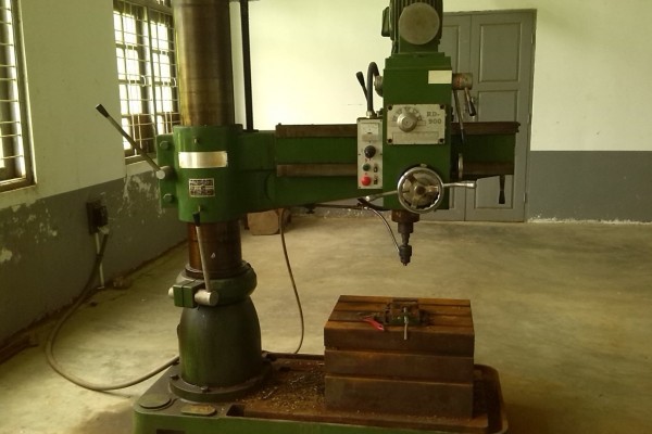
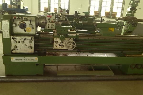
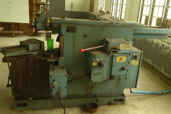
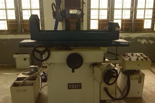
- Providing practical training through state-of-the-art laboratory facilities.
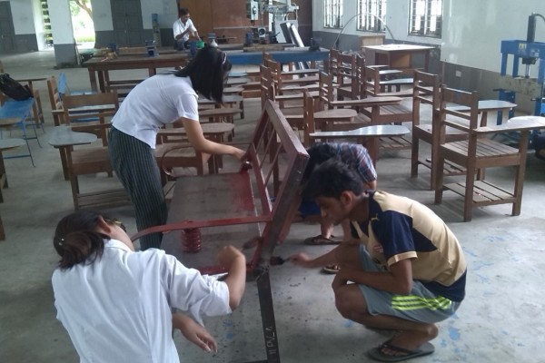
- Involving the students in innovative and group work exercises and projects useful for real-life applications.
- Preparing the students in developing research, design, entrepreneurial and employability capabilities.
- Providing consultancy services and promoting Industry-Department interactions.
- Enhancing the visibility of the Department through seminars, workshops and publications.
PROGRAMME EDUCATIONAL OBJECTIVES (PEOs)
- The Programme educational objectives of the students in Workshop Technology Department are:
- PEO 1: Provide students with the fundamental technical knowledge and skills in workshop and production engineering to recognize, analyze and solve problems, and to apply these abilities to the generation of new knowledge, ideas or products in industry or government; and to implement these solutions in practice.
- PEO 2: Provide students with the necessary instruction and practical experience to work well in local and international team environments and to be effective written and oral communicators, both for communicating ideas to other people, mentoring, and for learning from others.
- PEO 3: Produce students who recognize the importance of and engage in life-long learning, whether through self-study, continuing education courses or workshops, or through formal graduate level education and encourage others to have this same motivation.
- PEO 4: Produce students who have an understanding of ethical responsibility and service towards their peers, employers, and society and follow these precepts in their daily lives.
PROGRAMME OUTCOMES (POs)
- Students in Workshop Technology Department should at the time of their graduation be in possession of:
- 1. An ability to apply knowledge of workshop and production engineering fundamentals, and mechanical engineering for the solution of complex engineering problems.
- 2. Ability to identify, formulate, and solve engineering problems.
- 3. An ability to design and develop as model, component, or process to meet desired needs with in constraints such as economic, environmental, social, political, ethical, health and safety, manufacturability, and sustainability.
- 4. An ability to design and conduct experiments, as well as to analyze and interpret data.
- 5. Select and apply appropriate techniques, resources and modern engineering and IT tools, including prediction and modeling, to broadly defined engineering activities with an understanding of the limitations.
- 6. An understanding of professional, social and ethical responsibility.
- 7. The broad education necessary to understand the impact of engineering solutions in a global, economic, environmental, and societal context for sustainable development.
- 8. Commitment to professional ethics and norms of engineering practice.
- 9. An ability to function on multi disciplinary teams.
- 10. An ability to communicate effectively and prepare reports, documentations and presentations.
- 11. An ability to exhibit knowledge understanding and application management principles.
- 12. Recognition of the need for, and an ability to engage in life-long learning.
STAFF PROFILES
| Name: | Dr. Nan Oo |
| Academic: | A.G.T.I(Mechanical Power)Mandalay G.T.I, B.E (Mechanical) M.T.U,M.sc (Engineering,Liquid Rocket Engine) B.M.S.T.U (Russia), PhD (Mechanical) M.T.U. |
| Research Interest: | Mechanical Field in Space Technology |
| Post: | Associate Professor,Head of Department of Workshop Technology |
| Current Projects: | Teaching Aid Projects, Renewable Energy Project, Free Energy Project, Rocket Engine Project. |
| Publication: | “Design and Performance Parameters of Combustion Chamber and Nozzle of Liquid Fuel Small Thrust Engine”, The second international conference on science and engineering,3(2)(2010)24-28. |
| Name: | U Aung Soe Linn |
| Academic: | A.G.T.I(Machine Tools) Taungoo G.T.I,B-Tech(Mechatronics)M.T.U, B.E(Production)Y.T.U,M.E (Mechanical, Thesis) M.T.U |
| Post: | Lecturer |
| Current Projects: | Teaching Aid CNC Milling Machine Project, Renewable Energy Project, Free Energy Project. |
| Name | U Kyaw Kyaw Soe |
| Academic | B.E(Aeronautical) Y.T.U |
| Post | Lecturer |
| Current Project | Teaching Aid CNC Milling Machine Project, Free Energy Project. |
| Name | U Aung Myint Thein |
| Academic | A.G.T.I(Mechanical Power) |
| Post | Assistant Lecturer |
| Current Project | Teaching Aid CNC Milling Machine Project, Free Energy Project. |
| Name | U Myo Lwin Oo |
| Academic | A.G.T.I(Mechanical Power), B-Tech(Mechanical) |
| Post | Staff Officer (Laboratory) |
| Current Project | Teaching Aid CNC Milling Machine Project, Free Energy Project. |
| Name | U Kyaw Ko Ko |
| Academic | G.T.H.S (Mechanical Power) |
| Post | Crafts Man Mechanic (5) |
| Current Project | Teaching Aid CNC Milling Machine Project, Free Energy Project. |
Academic Year 2015-2016 Teaching Plan for First Term(Subject Code:WS-2001)
| Chapter | Topics/Sub-topics of Syllabus | Total Periods | Total Duration (Week) |
| 1 |
MEASURING INSTRUMENTS 1.1 Introduction 1.2 Steel Rule 1.3 Calipers 1.3.1 Outside Caliper 1.3.2 Inside Caliper 1.3.3 Odd-leg Caliper 1.4 Divider 1.5 Micrometers 1.5.1 Outside Micrometer 1.5.2 Inside Micrometer 1.5.3 Depth Gauge Micrometer 1.6 Vernier 1.6.1 Vernier Caliper 1.6.2 Vernier Height Gauge 1.6.3 Vernier Depth Gauge 1.7 Gauges 1.7.1 Radius Gauge 1.7.2 Feeler Gauge 1.7.3 Screw Pitch Gauge 1.7.4 Telescopic Gauge 1.8 Dial Indicator 1.9 Care of Instruments |
2 | 2 |
| 2 |
MEASURING TECHNIQUE 2.1 Test for Flatness 2.2 Test for Squareness 2.3 Test for Parallelism 2.4 Test for Roundness and Concentricity 2.5 Angular Test |
2 | 2 |
| 3 |
SAFETY IN WORKSHOP 3.1 Accidents 3.2 Machine tools and their hazards 3.3 Safety for Machine Shop 3.3.1 General Safety 3.3.2 Clothing and Safety Equipments 3.3.3 House Keeping 3.4 Safety for Arc Welding 3.4.1 Electric Shock 3.4.2 Poisoning with welding fume 3.4.3 Burn with arc ray 3.4.4 Burn with hot metal 3.4.5 Bruise |
2 | 2 |
| 4 |
BENCH WORK 4.1 Definition 4.2 Fitting Bench 4.3 Fitting Vice 4.3.1 Quick Acting Type 4.3.2 Fixed Type 4.4 Hammer 4.4.1 Ball Peen Hammer 4.4.2 Straight Peen Hammer 4.4.3 Cross Peen Hammer 4.4.4 Soft Hammer 4.4.5 Soft Face Hammer 4.4.6 Mallet 4.4.7 Safety for Hammer 4.5 Chisel 4.5.1 Flat Chisel 4.5.2 Cross Cut Chisel 4.5.3 Round Nose Chisel 4.5.4 Diamond Point Chisel 4.5.5 Safety for Chisel 4.6 Hacksaw 4.6.1 Frame 4.6.2 Blade 4.6.3 Causes of Accident 4.7 Fitting File 4.7.1 Length of File 4.7.2 Types of Section 4.7.3 Types of Cut 4.7.4 Grade of Cut 4.7.5 Safety for File 4.8 Taps 4.8.1 Types of tap 4.8.2 Tapping Method 4.9 Dies 4.9.1 Types of Die 4.9.2 Threading Method |
4 | 2 |
| 5 |
WELDING PROCESS 5.1 Introduction 5.2 Advantages of Welding 5.3 Disadvantages of Welding 5.4 Arc Welding 5.4.1 Carbon Arc Welding 5.4.2 Metal Arc Welding 5.5 Inert Gas Arc Welding 5.5.1 Tungsten Inert Gas Arc Welding 5.5.2 Metal Inert Gas Welding 5.5.3 Safety in Inert Gas Welding 5.6 Oxyacetylene Gas Welding 5.6.1 Adjustment of Flame 5.6.2 Basic Equipments of OAW 5.6.3 Comparison with Arc Welding |
4 | 2 |
| 6 |
CARPENTRY PROCESSES 6.1 Timber 6.1.1 Types of Timber 6.1.2 Advantages of Timber 6.1.3 Classification of Timber 6.1.4 Characteristics of Good Timber 6.1.5 Characteristics of Hard Wood 6.1.6 Characteristics of Soft Wood 6.1.7 Conversion of Timber 6.1.8 Market Forms Of Timber 6.2 Carpenter’s Tools 6.2.1 Marking, Measuring and Inspecting Tools 6.2.2 Cutting Tools 6.2.2.1 Saw 6.2.2.2 Axe 6.2.2.3 Chisel 6.2.3 Planing Tools 6.2.4 Boring and Drilling Tools 6.2.5 Fixing and Striking Tools 6.2.6 Holding and Miscellaneous Tools 6.3 Common Wood Joints 6.3.1 Butt Joints 6.3.2 Lap Joints 6.4 Common Wood Working Processes 6.5 Common Wood Working Machines 6.5.1 Wood Working Lathe 6.5.2 Circular Saw 6.5.3 Bend Saw |
6 | 2 |
| 7 |
MACHINE TOOLS 7.1 Classification Of Machine Tools 7.2 Definition 7.2.1 Metal Process 7.2.2 Machining 7.2.3 Machinability 7.3 Chief Elements of Metal Cutting 7.3.1 Chip Formation 7.3.2 Chip Thickness 7.3.3 Chip Width 7.3.4 Chip Cross Sectional Area 7.3.5 Cutting Speed 7.3.6 Feed 7.3.7 Depth of Cut 7.4 Machine Tool Principles 7.4.1 Forming 7.4.2 Generating 7.5 Force acting on Metal Cutting 7.5.1 Tangential Force 7.5.2 Radial Force 7.5.3 Feed Force 7.6 Power required in metal cutting 7.6.1 Specific Cutting Pressure 7.6.2 Horse power on Cutting Tool 7.6.3 Gross Horse power 7.6.4 Unit Horse power 7.7 Examples for metal cutting |
4 | 2 |
| 8 |
POWER IN THE WORKSHOP 8.1 Belt Drive 8.1.1 Types of belt 8.1.2 Types of belt drive 8.1.3 Drive mechanism 8.1.3.1 Direct drive 8.1.3.2 Countershaft drive 8.1.4 Power transmitted by a belt 8.2 Gear Drive 8.2.1 Simple gear drive 8.2.1 Gear train 8.2.2 Gear box of Colchester lathe head 8.2.3 Calculation for spindle speeds |
4 | 2 |
| 9 | Tutorial | 4 | 2 |
Academic Year 2015-2016 Teaching Plan for Second Term(Subject Code:WS-2001)
| Chapter | Topics/Sub-topics of Syllabus | Total Periods | Total Duration (Week) |
| 9 |
CUTTING TOOL ANGLES 9.1 Tool Nomenclature 9.1.1 Definitions of tool parts 9.1.2 Three Views of single point tool 9.2 Tool Angles 9.3 Tool Signature 9.4 Selection of Angles 9.5 Recommended angle for H.S.S Tool 9.6 Effected Angles 9.7 Calculation for effected angles |
4 | 2 |
| 10 |
CUTTING TOOL MATERIALS 10.1 Introduction 10.2 Selection of Tool Materials 10.3 Properties of Tool Materials 10.3.1 Wear Resistance 10.3.2 Red Hardness 10.3.3 Toughness 10.3.4 Others 10.4 Classification of Tool Materials 10.4.1 High Carbon Steel 10.4.2 High Speed Steel 10.4.3 Tungsten Carbide 10.4.4 Ceramics |
2 | 2 |
| 11 |
ENGINEERING MATERIALS 11.1 Introduction 11.2 Mechanical Properties of materials 11.3 Commercial Testing of materials 11.3.1 Tensile Test 11.4 Iron 11.4.1 Pig Iron 11.4.2 Wrought Iron 11.4.3 Gray Cast Iron 11.5 Plain Carbon Steel 11.5.1 Low Carbon Steel 11.5.1.1 Mild Steel 11.5.1.2 Dead Mild Steel 11.5.2 Medium Carbon Steel 11.5.3 High Carbon Steel 11.6 Alloy Steel 11.7 Heat Treatment 11.8 Non-ferrous Metals and Alloys 11.8.1 Aluminium 11.8.2 Copper 11.8.3 Tin 11.8.4 Lead 11.8.5 Zinc 11.8.6 Bronze 11.8.7 Brass |
4 | 2 |
| 12 |
FOUNDRY 12.1 Definition 12.2 Casting 12.3 Pattern 12.3.1 Definition 12.3.2 Pattern making 12.3.3 Pattern Allowance 12.3.4 Types of Pattern 12.4 Sand Mould 12.5 Core 12.6 Gate 12.7 Riser 12.8 Cleaning and Finishing 12.9 Inspection 12.9.1 Destructive Test 12.9.2 Non-Destructive Test |
2 | 2 |
| 13 |
SMITHY AND FORGING 13.1 Introduction 13.2 Forgeable Materials 13.3 Factors in Forging 13.3.1 Metallurgical Factor 13.3.2 Mechanical Factor 13.4 Forging Temperature 13.5 Grain Flow in Forging Parts 13.6 Advantages of forging 13.7 Disadvantage of forging 13.8 Forging Operations 13.8.1 Upsetting 13.8.2 Drawing Dawn 13.8.3 Cutting 13.8.4 Bending 13.8.5 Punching and Drifting 13.8.6 Setting Dawn 13.8.7 Fullering 13.8.8 Swaging 13.8.9 Flattening 13.8.10 Forge Welding 13.9 Forge or Furnace 13.10 Forging Tools 13.10.1 Anvil 13.10.2 Hammer 13.10.2.1 Hand Hammer 13.10.2.2 Sledge Hammer 13.11 Hand Tools 13.11.1 Chisel 13.11.2 Fuller 13.11.3 Swage 13.11.4 Swage Block 13.11.5 Flatter and Set Hammer 13.11.6 Punch and Drift 13.11.7 Tong |
4 | 2 |
| 14 |
INTERCHANGABLE SYSTEM 14.1 Terms and Definitions 14.1.1 Limits 14.1.2 Tolerance 14.1.2.1 Unilateral Tolerance 14.1.2.2 Bilateral Tolerance 14.1.3 Allowance 14.1.4 Sizes 14.1.4.1 Nominal Size 14.1.4.2 Basic Size 14.1.4.3 Design Size 14.1.4.4 Actual Size 14.2 Types of Fit 14.2.1 Clearance Fit 14.2.2 Interference Fit 14.2.3 Transition Fit 14.3 Basic System 14.3.1 Hole System 14.3.2 Shaft System 14.4 Problems for Limits |
2 | 2 |
| 15 |
ESTIMATION IN MACHINE SHOP 15.1 Introduction 15.2 Machine Time for Turning 15.3 Machine Time for Facing 15.4 Machine Time for Drilling 15.5 Determination of Tap Diameter Size 15.6 Machine Time for Tapping 15.7 Machine Time for Threading 15.8 Machine Time for Shaping 15.9 Machine Time for Milling |
4 | 2 |
| 16 |
UNCONVENTIONAL METHOD OF MACHINING 16.1 Introduction 16.2 Types of Unconventional Methods 16.2.1 Abrasive Jet Machining 16.2.1.1 Construction 16.2.1.2 Operation 16.2.1.3 Advantages and Disadvantages 16.2.1.4 Fluid Jet Machining 16.2.2 Electron Beam Machining 16.2.2.1 Construction 16.2.2.2 Operation 16.2.2.3 Advantages and Disadvantages 16.2.3 Plasma Arc Machining 16.2.3.1 Construction 16.2.3.2 Operation 16.2.3.3 Advantages and Disadvantages |
2 | 2 |
| 17 |
NUMERICAL CONTROL SYSTEM 17.1 Fully Automatic System 17.2 Open Loop Control System 17.3 Close Loop Control System 17.4 Definitions of G Code, M Function and Others 17.5 Definition of X Axis and Z Axis 17.6 Definition of Absolute and Incremental Mode 17.7 Programs for given workpiece according to each mode |
4 | 2 |
Academic Year 2015-2016 Teaching Plan for First Term(Subject Code:WS-5001)
| Chapter | Topics/Sub-topics of Syllabus | Total Periods | Total Duration (Week) |
| 1 |
INTRODUCTION 1.1 Production Planning 1.2 Product Manufacturing 1.3 Product Inspection |
6 | 12 |
| 2 |
Quality Control 2.1 Sorting Defective Items 2.2 Statistical Quality Control 2.2.1 Fundamental Concept of Statistics 2.2.2 Frequency Distribution Diagram 2.2.3 Samples Means Frequency Diagram 2.3 Central Limit Theorem 2.4 Process Control Charts 2.4.1 and R Chart 2.4.2 Warning Lines on the X Chart and R Chart 2.5 Rule of Seven 2.6 Chart Review and Action 2.7 Calculation of Standard deviation from Sample Mean range 2.8 Performance Limits of a Process and Specification limits of a Product 2.9 Relative Precision Index (R.P.I) 2.9.1 Classification Table for R.P.I 2.10 P Chart: Process Control Chart for Attributes 2.10.1 Frequency Distribution for Sample Fraction Defectives (P distribution) 2.11 Sampling Inspection (Acceptance sampling) 2.11.1 Applications 2.12 Operating Characteristic Curve (OC curve) of a Sampling Plan 2.13 Calculation of Probability of Acceptance L(P′) 2.14 Double Sampling Scheme 2.15 Cost of Inspection |
15 | 5 |
| 3 |
MEASURMENT AND GAGING 3.1 Manufacturing Specifications 3.2 Tolerances 3.2.1 Ways of Specifying Tolerances 3.2.2 Methods of Assigning Tolerances 3.3 Limits and Fits 3.4 Choosing of Manufacturing Tolerances 3.5 Assembly Methods 3.6 Assigning Tolerances to Mating Parts 3.7 Determination of Tools for Given Allowance of Two Mating Parts 3.7.1 For 100% Interchangeability 3.7.2 For Statistical Average Interchangeability 3.8 Alternative Method for Calculating Tolerance for Two mating Parts for 100% interchangeability 3.9 Geometric Dimensions and Tolerances 3.10 Gages 3.10.1 Measuring with Light Rays |
12 | 4 |
| 4 |
GEARS AND GEAR MANUFACTURE 4.1 Introduction to gears 4.2 Gear tooth curves 4.3 Elements of gear teeth 4.4 Types of gears 4.4.1 Classification of gears 4.5 Introduction to gear manufacturing 4.6 Forming gear teeth 4.6.1 Casting 4.6.2 Sintering or P/M process 4.6.3 Injection molding 4.6.4 Extruding 4.6.5 Cold drawing 4.6.6 Stamping 4.6.7 Pre-forming 4.6.8 Forging 4.7 Machining 4.7.1 Roughing processes 4.7.1.1 Gear form-cutting 4.7.1.2 Gear generating 4.7.2 Finishing processes 4.8 Gear inspection 4.8.1 Checking the sizes of gears and gear teeth 4.8.2 Checking gear tooth profile 4.8.3 Checking the positions of gear teeth 4.8.4 Checking gear tooth bearing and surface finish 4.8.5 Checking for noise |
15 | 5 |
Academic Year 2015-2016Teaching Plan for Second Term(Subject Code:WS-5001)
| 5 |
METAL CUTTING 1.1Introduction 1.2Terms and definitions 1.3Chip formation 1.3.1Continuous chip 1.3.2Continuous chip with built up edge 1.3.3Discontinuous chip or segmental chip 1.4The forces acting on the cutting tool and their measurement 1.5Specific cutting energy in machining 1.6Metal cutting theory 1.7Cutting tool shape for orthogonal cutting 1.8Cutting theory 1.8.1 Coefficient of friction 1.8.2 Determining shear plane angle 1.8.3 Chip thickness ratio 1.8.4 Velocity system of cut 1.8.5 Shear strain of chip 1.8.6 Shear stress 1.8.7 Power required for machining 1.9 Basic metal cutting theory by Ernst& Merchant 1.9.1 Modified theory |
15 | 5 |
| 6 |
COMPUTER NUMERICAL CONTROL 1.1 Introduction 1.1.1 Definition 1.1.2 Applications 1.1.3 Advantages and limitations 1.2 Elements of a CNC 1.2.1 Part program 1.2.2 Machine control unit 1.2.3 Machine tools 1.2.3.1 Machines using CNC 1.3 Principles of CNC 1.3.1 Basic length unit 1.3.2 Cartesian coordinate system 1.3.3 CNC positioning systems 1.3.4 Interpolation 1.3.5 positioning reference point systems 1.3.6 Work coordinates 1.3.7 Machine zero point or machine home 1.3.8 Work settings and offsets 1.3.9 Tool length offset 1.3.10 Control loop systems 1.4 Precision in CNC machining 1.5 Part programming for CNC 1.5.1 Programming format 1.5.2 Word address format 1.5.3 Codes |
21 | 7 |
| 7 |
METAL SHEARING AND FORMING 1.1Metal shearing operations 1.2Principle of metal shearing 1.3Bending 1.4Drawing 1.5Metal spinning 1.6High energy rate forming 1.7Squeezing 1.8Press 1.9Stock feeding devices 1.10Safety devices |
12 | 4 |
Marking Scheme for WS-2001 (Workshop Technology)
| 100 Marks | Remark | |||||||
| Exam | 70% | Tutorial | 5% | Practical | 15% | Class Room Performance (Practical Performance Test) | 10% | |
| 1st Exam | 35% | Tutorial | Roll Call | 5% | Theory Understanding | 2% | ||
| 2nd Exam | 35% | Job Mark | 5% | Instrument Application | 2% | |||
| Job Report | 5% | Instruct | 2% | |||||
| Unity | 2% | |||||||
| Result | 2% | |||||||
Marking Scheme for WS-5001(Production Technology)
| Theory Understanding | 20 |
| Instrument Application | 20 |
| Interest | 20 |
| Unity | 20 |
| Finishing | 20 |
| Total | 100 |
| 100 Marks | Remark | |||||||
| Exam | 70% | Tutorial | 10% | Practical | 10% | Class Room Performance | 10% | |
| 1st Exam | 35% | Tutorial | Assignment | 5% | Roll Call | 2% | ||
| 2nd Exam | 35% | |||||||
| Practical | 5% | Oral Test | 2% | |||||
| Tutorial Test | 3% | |||||||
| Practical Test | 3% | |||||||
